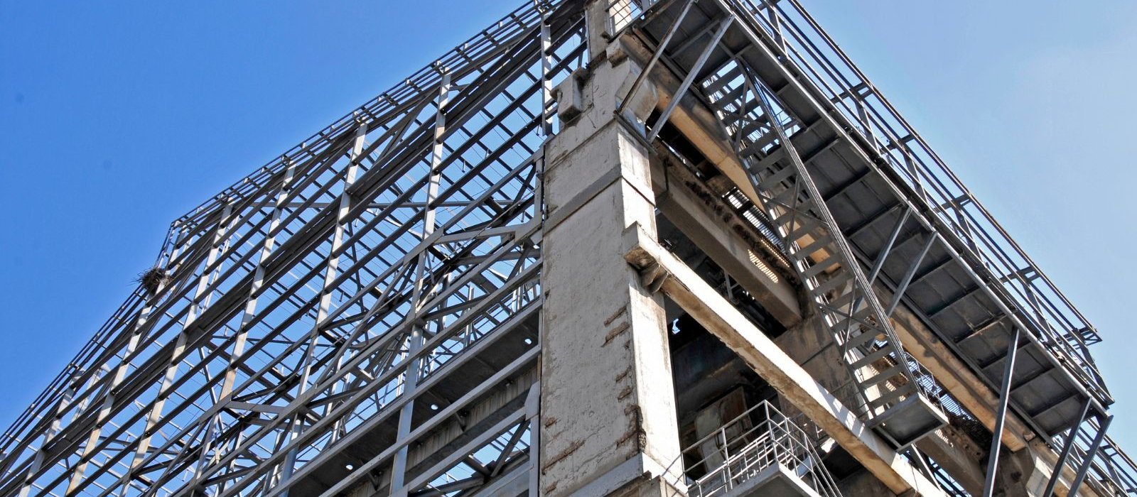
When does a building project need CFD-based wind analysis beyond code values? Complex geometry, interference effects, cladding pressure — a practical guide for structural and façade engineers.
Building codes provide wind load values that cover a broad range of standard building geometries reasonably well. For a rectangular mid-rise building in an open exposure, code-prescribed pressure coefficients are appropriate and conservative.
But as buildings become taller, more slender, more geometrically complex, or more closely surrounded by other structures, code-based wind loads become progressively less accurate. At some point, they either significantly overestimate loads — driving unnecessary structural cost — or, more dangerously, miss local pressure concentrations that the code's simplified geometry couldn't capture.
This article covers when code-based wind calculation is sufficient, when it isn't, and what the alternatives look like.
How Code-Based Wind Load Calculation Works
Building codes — ASCE 7, Eurocode 1 Part 1-4, and local equivalents — prescribe wind loads through a combination of:
- Basic wind speed at the project location, from code-provided maps
- Exposure category based on the surrounding terrain roughness
- Height-dependent wind speed profile — wind speed increases with height
- Pressure coefficients (Cp or Cpe) — dimensionless multipliers that translate wind speed into surface pressure, tabulated for a limited set of building shapes
The resulting design pressures are applied as static equivalent loads to the structural system.
This approach works well for buildings that broadly resemble the shapes for which the code coefficients were derived — predominantly rectangular plans, moderate aspect ratios, and exposure conditions reasonably consistent with the code's assumptions.
When Code Values Are Not Adequate
The code approach has inherent limitations that become significant in a number of situations:
Complex or Non-Rectangular Geometry
Curved facades, irregular floor plates, tapering towers, large roof overhangs, or canopy structures fall outside the scope of code pressure coefficient tables. The flow patterns around these geometries generate local pressure distributions that cannot be captured by coefficients derived from simple rectangular forms.
Applying rectangular building coefficients to a complex geometry will produce pressures that are inaccurate — sometimes conservative, sometimes not — and cannot be verified without more sophisticated analysis.
Tall or Slender Structures
For slender high-rise buildings, wind-induced dynamic effects — particularly across-wind excitation and vortex shedding — can dominate the structural response. Code static equivalent loads do not adequately capture these effects.
Across-wind loads can be larger than along-wind loads for slender buildings (height-to-width ratios above approximately 4:1). The dynamic amplification depends on the building's natural frequency, damping, and the turbulence characteristics of the wind — all of which require analysis beyond the code's static equivalent approach.
Interference Effects from Neighbouring Buildings
The presence of neighbouring buildings significantly alters the wind environment around a structure. Wake effects, channelling between buildings, and corner accelerations can produce local pressure increases substantially above what isolated building coefficients would predict.
Building codes do not account for specific neighbour configurations. If a project site is in a dense urban environment with closely spaced buildings, interference effects need to be assessed.
Cladding and Façade Pressure Requirements
Structural codes provide overall lateral load values for the primary structure. Local pressures on cladding panels, glazing, and façade elements — particularly at corners, edges, and roof perimeters — often require more detailed analysis. Code corner pressure coefficients are conservative in aggregate but may not capture the spatial distribution of pressures that governs individual cladding panel design.
Pedestrian Wind Comfort
Wind at ground level around buildings affects pedestrian comfort and safety. Code calculations provide no information on ground-level wind conditions — this requires either CFD analysis or wind tunnel testing.
Alternatives to Code-Based Calculation
CFD Wind Analysis
Computational Fluid Dynamics (CFD) analysis simulates wind flow around the building geometry, resolving pressure distributions on all surfaces simultaneously. The flow field can include surrounding terrain and neighbouring buildings.
CFD wind analysis is particularly useful for:
- Complex building geometries where code coefficients don't apply
- Local cladding pressure distributions
- Pedestrian wind comfort assessment
- Initial studies before committing to wind tunnel testing
The accuracy of CFD wind analysis depends critically on the turbulence modelling approach and the boundary conditions used to represent the atmospheric boundary layer. RANS-based methods (steady-state Reynolds-Averaged Navier-Stokes) are the standard approach for buildings — faster than LES (Large Eddy Simulation) and adequate for mean pressure predictions, though less accurate for peak pressure estimation in separated flow regions.
The analysis should include a sensitivity study on turbulence model parameters and mesh density. Results without a documented validation strategy should be treated with caution.
Wind Tunnel Testing
Wind tunnel testing remains the highest-fidelity method for building wind loads, particularly for tall buildings and complex projects where dynamic effects and interference are significant.
A scale model of the building and its surroundings is tested in a boundary layer wind tunnel that simulates the turbulent characteristics of the atmospheric boundary layer. Pressure taps on the model surface directly measure surface pressures at hundreds of locations simultaneously.
The results of wind tunnel testing are used to:
- Determine structural loads (base shear, overturning moment, torsion)
- Establish cladding pressure zones
- Assess accelerations for occupant comfort in tall buildings
- Evaluate pedestrian wind conditions
Wind tunnel testing is more expensive than CFD analysis and requires physical model fabrication. For most projects requiring wind analysis beyond code, CFD provides sufficient accuracy at substantially lower cost. Wind tunnel testing is generally reserved for tall buildings above approximately 150–200 m, or for particularly complex or high-profile projects.
What a CFD Wind Analysis Report Should Contain
A credible CFD wind analysis report includes:
Computational domain and boundary conditions: Domain dimensions, inlet velocity profile, turbulence intensity, and justification for these choices relative to established guidelines (COST Action 732, AIJ guidelines, etc.)
Mesh strategy: Domain mesh density, refinement zones around the building, near-wall treatment, and mesh independence study.
Wind direction coverage: For most projects, sixteen wind directions at 22.5° intervals. Critical directions identified and reported separately.
Pressure coefficient maps: Surface pressure distributions on all façades for each wind direction. Comparison with code values where applicable.
Peak pressure estimation: Mean pressures from RANS analysis should be combined with appropriate peak factors for cladding design. The method for estimating peaks should be documented.
Structural load summary: Integrated forces and moments on the structure for use in the global structural model.
Summary
Code-based wind loads are adequate for standard building forms in straightforward exposure conditions. For complex geometries, tall or slender structures, urban interference effects, and detailed cladding pressure requirements, more sophisticated analysis is necessary.
CFD wind analysis provides a cost-effective route to accurate, geometry-specific wind loads. The quality of the result depends entirely on the quality of the setup — turbulence modelling, boundary conditions, mesh strategy, and validation — and these should be explicitly documented in any analysis report.
If your project involves complex geometry, tall structures, or cladding pressure requirements beyond standard code values, share your scope.