This paper will detail the thermal design and analysis of the instrument, which includes both the control electronics and crystal detector units (CDUs).
The StarBurst Multimessenger Pioneer is a small satellite serving as a wide-field gamma-ray observatory designed to detect the initial emissions of short gamma ray bursts, electromagnetic indicators of neutron star mergers. This paper will detail the thermal design and analysis of the instrument, which includes both the control electronics and crystal detector units (CDUs). The CDUs are a critical component essential to mission success and have the narrowest temperature range, however the CDU thermal model is low fidelity at the time of Critical Design Review (CDR) before a final CDU design is completed. Therefore, a more detailed CDU model is created for post-CDR analysis to update the passive Thermal Control System (TCS) design and efficiently maintain the operational and survival temperature limits with minimal heater power. Including the additional detail is necessary to determine the final Multilayer Insulation (MLI) design, including material selection and coverage, coating selection, and required heater power.
StarBurst Background
Critical Design Review (CDR) Thermal Analysis & Design
– Overview
– Spacecraft
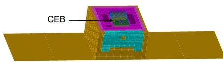
– Instrument Control Electronics Box (CEB)
– Instrument Crystal Detector Units (CDU)
– Passive Thermal Control System (TCS)
– Thermal Environments
– Results
– Known Deficiencies
Post-CDR Thermal Analysis & Design
– Instrument CDUs
– Heat Dissipations
– Spacecraft
– Passive TCS
– Results
Conclusions
Acknowledgements
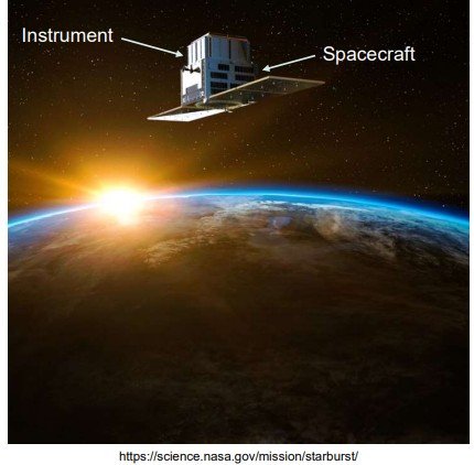
The StarBurst Multimessenger Pioneer is a highly sensitive and wide field gamma-ray monitor designed to detect the prompt emission of short gamma-ray bursts (SGRBs), a key EM signature of neutron star mergers.
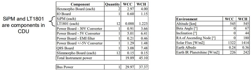
The StarBurst instrument consists of 12 Crystal Detector Units (CDUs) to detect these gamma-rays, and associated electronics.
StarBurst Partnership Roles:
– NASA Marshall Space Flight Center (MSFC): Principal Investigator institution and overall project management
– Naval Research Lab (NRL): StarBurst instrument design and fabrication
– University of Alabama Huntsville (UAH): Instrument flight software
– University Space Research Alliance (USRA): Science operations center
– University of Toronto Institute for Aerospace Studies (UTIAS) Space Flight Lab (SFL): Spacecraft bus and mission operations center.
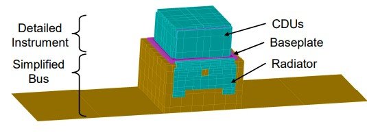
NASA MSFC thermal model
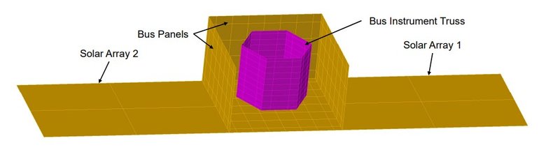
– Simplified spacecraft bus model
• Spacecraft
• Solar Arrays
• Instrument Truss
– Detailed instrument model
• Crystal Detector Units (CDUs)
• Control Electronics Box (CEB)
• Baseplate & Support Structure
• SFL thermal model
– Detailed spacecraft bus model
– Simplified instrument model
SFL provided details
– Materials and optical properties of spacecraft panels, internal truss, and solar arrays
– Thermal contacts between bus components
– Thermal contact between spacecraft bus panel and baseplate
– Total bus heat dissipation, max and min
• Bus instruments are mounted to internal instrument truss so heat dissipation is evenly distributed across all instrument truss surfaces in the simplified model.
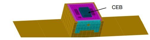
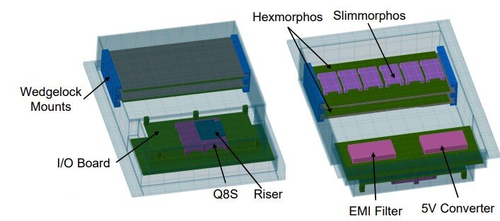
Control Electronics Box (CEB) components
– Hexmorphos x2
– Slimmorphos x12
– Power Board
• 5V converter
• EMI filter
– I/O Board
– Xiphos Q8S processor
– Standoffs
Key design aspects
– Hexmorphos
• Mounted to aluminum mounting plane
• Al mounting plane mounted via Wedgelocks
– Xiphos Q8S
• Using CoolZorb Ultra Thermal Interface Material (TIM)
• A riser is machined into the enclosure for increased heat transfer
– CEB mounted to baseplate
– Thermal contacts
• Heat transfer through Wedgelocks is based on specific part number datasheet
• Heat transfer through TIM is based on material datasheet and compression
• Power board is bolted directly to enclosure shelf
• Contacts between boards and standoffs are based on bolting parameters (bolt number, bolt diameter, torque, and contact area)
– Material properties
• Printed Circuit Boards (PCBs) thermophysical properties are anisotropic and based on specific copper content of each board
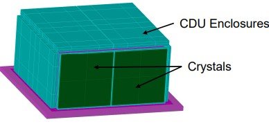
Crystal Detector Units (CDUs) components
– Enclosures
– Crystals
– Sodium Iodide
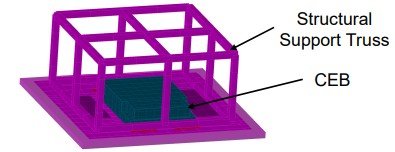
Support structure components
– Baseplate
– Structural support truss
Key design aspects
– Baseplate is based on NRL design CAD
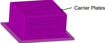
– Structural support including truss and carrier plates are assumptions
– Thermal contacts
Thermal contacts between truss, carrier plates, and CDU enclosures are assumed
Thermal contacts between crystals and enclosure are based on preliminary design of CDU
Radiator
– Designed by SFL as part of spacecraft design
– Outward facing coating = Z93 white paint (α=0.17, ε=0.92)
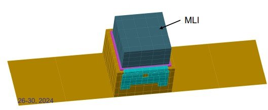
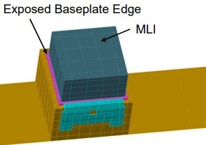
MLI
– Modeled effective emissivity ε*=0.05
– Outer layer = aluminized beta cloth (α=0.22, ε=0.3)
– MLI coverage leaves 1’’ of baseplate perimeter exposed
• Exposed portion of baseplate is covered with silver-Teflon tape (α=0.05, ε=0.68)
• Effectively adds radiator area
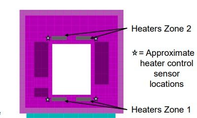
Heaters
– Locations determined by NRL, parameters defined by SFL
– Four 1x4’’ Kapton heaters on baseplate
– Set points on/off = -21/-23C
– Each heater is controlled by an individual temperature sensor next to the heater location
Environments are bracketed by Worst-Case-Cold (WCC) and Worst-Case-Hot (WCH) assumptions
Model Cases include:
– WCH Operational
– WCC Operational
– WCC Non-Operational
Instrument heat dissipation is 0W, spacecraft heat dissipation is the WCC assumption
CDR Margin: +/-10C
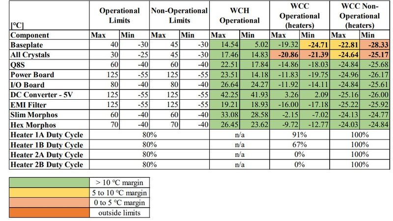
Observations to note:
– In WCC environments, crystals are cold despite heaters turning on
– Baseplate “requirement” is more of a perceived design solution than a hardware limit
CDU and structural support truss is low fidelity
– The CDUs are critical science-measuring components, yet represented in low fidelity
– The CDU design down-select was completed recently prior to CDR
MLI coverage is unreliable
– Graphical representation of the MLI does not account for significant thickness
– The attachment of the MLI to the baseplate would need to be very precise to expose the exact amount of baseplate needing to be exposed
Heaters are designed to control the baseplate temperature within the baseplate temperature limit defined in the requirements, not to control the CDU temperatures within limits
These design deficiencies were known prior to CDR, however the decision was made to update the fidelity of the CDUs and structural support postCDR, after CDU design down-select, and use the updated model to adjust the TCS
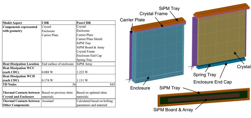
The CDU was modeled in greater detail as a separate thermal model and block-referenced into the system model for each CDU
– Geometry based on updated CAD design
– Crystal material updated to Cesium Iodide